Posted on

A Beginner’s Guide to MIG or Metal Inert Gas Welding

Welding is the backbone of the modern metalworking industry. Whether in a manufacturing unit or a repair workshop, you will usually find some type of welding machine everywhere.

There are many different methods of arc welding, including MIG, TIG, SAW and PAW. MIG welding is suitable for many applications and is particularly suitable for welding thick metal sheets and can also be used for very thick sections.

How does MIG welding work? And what is MIG welding used for?

In this article, we will introduce the MIG welding process and examine where and when to use it.

What is MIG Welding?

MIG definition: A welding process that fuses metals together using a consumable wire electrode shielded by an inert gas. The MIG welding process was developed in 1948 by The Battelle Memorial Institute and patented in 1949.

MIG welding is one of the two sub-types of Gas Metal Arc Welding (GMAW), the other being Metal Active Gas (MAG) Welding. The process and equipment are the same, the definition comes from the type of shielding gas used, for example, if inert argon gas is used as the shielding gas it is a MIG process. If active helium gas is used it is a MAG process. The choice of which type of shielding gas to use is determined by the metals to be welded.

What Metals Can Be MIG Welded?

MIG welding works for almost all metals, including (but not limited to) mild steel, stainless steel, aluminium, copper, magnesium, bronze and nickel. MIG welding is suitable for most metal thicknesses. However, it is usually not the preferred method for thin sheets because of the risk of burning through the sheet, although advances in the characteristics of modern MIG/MAG welding equipment have made this possible.

How MIG Welding Works – Process Characteristics

MIG welding is an arc welding process that uses a continuous solid wire electrode heated and fed into the weld pool from a welding gun. The two base materials are melted together forming a join. The gun feeds a shielding gas alongside the electrode helping protect the weld pool from airborne contaminants and keeps oxygen out of the molten metal.

In MIG welding, the operating works with a MIG welding torch, or ‘gun’. When the torch trigger is pressed:

  • The torch starts to feed welding wire from a spooled wire feed unit.
  • An electrical arc is created between the welding wire and workpiece, which heats the workpiece, melts the wire and fuses it to the joint area.
  • The torch releases a shielding gas flow to shield the junction of the workpiece and the melted wire from a nozzle around the wire in the torch.

For a more detailed understanding, we will examine the key features of the MIG welding process.

Metal Transfer Mode

MIG welding works by using an arc to melt the base material and feed filler wire metal into it. The joint is formed as a mixture of the filler metal wire and the base metal.

The method by which the filler wire is transferred into the weld pool can be done in several different ways, the choice of which method to use is dependent on the position of the weld, (for example upside down,) and the type and thickness of the material being welded. The four most common transfer types are described here:

Short Circuit Mode or Dip Transfer

In short circuit or dip transfer mode, the speed of the wire feeding into the weld pool is increased so that it physically touches the weld pool. The short circuit melts the wire and deposits it in the weld pool. These short circuits can take place 20 – 200 times per second.

For the wire, either solid wire or solid-cored wire is used. It is a low voltage and low heat input welding method.
The short circuit method can be used in all positions, vertical up, vertical down, horizontal, or overhead. Typical shielding gas is 75%-85% argon.

Globular Mode

In globular mode, a continuous arc is maintained between the wire and the workpiece and the metal is transferred to the weld pool as droplets.

Creating these large drops of metal requires a high amount of heat. The diameter of the metal droplets is much greater than the diameter of the wire.

In globular mode, welding can be done at high speed but not for positional welding as the droplets fall into the weld pool by gravity. Typical shield gas is pure CO2, which makes it an inexpensive method. However, globular transfer can create a lot of spatter and looks unsightly so additional post-weld cleaning processes may be required.

Spray Mode

Unlike the short circuit and globular mode, the spray transfer mode occurs at a high voltage, typically >25V for a 1mm diameter wire. The wire feed speed is adjusted to give more than 250A and the welding arc burns continuously. Metal melts from the wire and passes across the arc in a series of small droplets, called spray transfer. This mode of transfer consists of a ‘spray’ of very small molten metal droplets which are projected towards the workpiece by electrical forces within the arc. The diameter of the droplets is typically 0.5 – 1 times the diameter of the electrode wire and the resulting weld bead is usually clean and aesthetically pleasing with low spatter. This mode of transfer is not suited to positional welding, although it can be used for positional welding of aluminium and its alloys.

Pulse Mode

Unlike the methods mentioned above, the pulse metal transfer mode requires dedicated MIG welding machines with pulse MIG functionality.

In its simplest form, this consists of a period at a background current that maintains the arc but does not achieve metal transfer, followed by a period of high current during which spray transfer occurs. The average current is midway between background and peak and can be well below the threshold normally associated with spray transfer. This means that the weld pool size is relatively small and positional welding is possible even though the transfer mechanism is spray. Pulsed MIG welding is all positional and produces clean weld beads with minimal spatter and a reduced heat-affected zone. It is suitable for thin or thick materials. The shielding gas for pulsed MIG is typically argon.

How MIG Welding Works – Components

Wire Electrode/Filler Metal

The welding wire acts as a consumable electrode that creates the arc. The wire serves as both the source of the heat, (via the arc at the contact tip) and filler metal for the joint and is fed through a copper tube called a contact tip, which conducts current into the wire. The choice of filler metal is dependent on the materials being joined, generally, the same type of metal grade will be used, for example, low alloy filler wires to join low alloy steels and stainless steel wires for stainless steel joints. Also, the mechanical and corrosion-resistant properties of the filler metal must match, or better still overmatch the properties of the base metal. If in doubt the manufacturers of both the base metal and the filler metal can advise on what they would recommend. Typical diameters of wire for MIG welding are from 0.8mm up to 1.6mm and again the choice is dependent on the joint configuration and thickness of the material.

Shielding Gas

The shielding gas isolates the weld pool from the atmosphere, so the molten metal does not oxidise. The shielding gases most commonly used are argon, helium, and carbon dioxide. Usually, a mixture of these gases is used instead of pure gases, with the ratio depending on the type of base metal, type of weld metal, and the mode of metal transfer.

Welding Torch

The MIG welding torch connects to the welding power source with a cable that carries the electrical current, welding wire and shielding gas. It has a trigger switch that turns on the electric arc, releases the shielding gas, and starts the wire feed at the same time. At the working end of the torch, a contact tip guides the wire and acts as a conductor for the welding arc between the torch and filler metal. This copper contact tip wears out through use and is a consumable that needs to be replaced after some hours of welding. The diameter of the hole in the contact tip is suited to the diameter of the wire going through it.

Power Source

Welding takes place at relatively low voltage compared with the input mains electricity and much higher current. Any variation in the arc length, that is the distance between the filler wire and the base metal, causes a change in the voltage. With the MIG welding process requiring the wire to be constantly fed into the weld pool then in order to ‘smooth’ this out the power supply for MIG welding is required to deliver a constant voltage to the torch.  The selection of the power source is dependent upon the thickness of the base metal, the material type and the number of hours that the machine will be running in a day.

Advantages of MIG Welding

Advantages of MIG welding include:

Versatility

MIG welding is a highly versatile welding process, suitable for many different types, sizes and thicknesses of metals and in all welding positions.

Automation

MIG welding can readily be mechanised or fully automated. A high-speed robotic or semi-automatic setup offers faster MIG welding with more consistent results.

Weld Bead Aesthetics

MIG welding offers an attractive weld bead that does not ruin the appearance of the joints. There is minimal spatter and visible heat-affected zones. The finished MIG weld is visually appealing.

Disadvantages of MIG Welding

While MIG welding is a popular welding technique, the process has the same limitations as with all welding processes:

Burn Through

Burn through occurs when the base metal completely melts, and the molten metal of the weld falls through. There is a possibility of burn-through when MIG welding thin metals in globular or spray transfer modes. Short circuit transfer is more appropriate for thinner metals.

Lack of Fusion

Lack of fusion is a type of weld defect which occurs when the molten metal, the weld pool, does not completely fuse with the cold base metal and is more prevalent in thicker materials. For this reason, spray transfer mode is advised for MIG welding thicker materials.

Shielding Gas

For MIG welding that requires a higher percentage of argon, the overall cost of the welding process is increased since argon is one of the most expensive inert shielding gases. Also because of the requirement of a shielding gas for this process, it is not easy to use outside of the workshop. Any draughts will blow the shielding gas away from the end of the torch.

Positional Limitations

MIG Welding in globular and spray Transfer modes limits the weld position. You can only use these methods in a horizontal or flat position.

MIG Welding Applications

What is a MIG welder used for? MIG welding is the primary method for metal welding in industry, with more than 50% of the global welded metal done with a MIG welder.
MIG welding is common in the automotive industry where the all-positional properties of the process and the wire filler being fed from a spool lend itself to automation; the torch is attached to a robotic arm.  Besides the automotive segment, many other industries that are fabricating sheet metal, pipes, thick section beams for construction, shipyards and general workshops also use the MIG welding process.

Conclusion

MIG welding is one of the most popular welding methods used by both amateurs and professionals. This is partly due to the benefits it offers and partly due to its ease of use.
While the technical feature of a MIG welding power-source can help improve your weld quality, the best way to improve your results is to practise your welding technique and optimise the settings for the metal and filler you are welding. For advice on the choice of power supply, filler wire, shielding gas and welding parameters ESAB have skilled welding engineers who can assist.

Using high-quality MIG welding equipment will make your job a lot easier. Check out ESAB’s range of industrial MIG welding equipment and high-quality filler metals and ensure you have the right tools for your job!
Posted on

Comparing TIG and MIG Welders: Which is Right for You?

Welding is a fundamental process in metalworking and fabrication, and choosing the right welding method can significantly impact the quality and efficiency of your projects. Two of the most popular welding techniques are MIG Welding vs. TIG Welding, Tungsten Inert Gas (TIG) welding and Metal Inert Gas (MIG) welding. Each has its strengths, applications, and limitations. This article provides a detailed comparison of TIG and MIG welders to help you decide which method is best suited for your needs.

Understanding TIG Welding

What is TIG Welding?

TIG welding, also known as Gas Tungsten Arc Welding (GTAW), uses a non-consumable tungsten electrode to produce the weld. The weld area is protected from atmospheric contamination by an inert shielding gas, typically argon or helium. A filler metal may or may not be used, depending on the application.

Advantages of TIG Welding Machines

  1. Precision and Control: TIG welding offers exceptional control over the weld, making it ideal for detailed and delicate work. The ability to adjust the heat input with a foot pedal or fingertip control allows for precise welds.
  2. High-Quality Welds: The process produces clean, high-quality welds with minimal spatter, making it suitable for critical applications where appearance and strength are paramount.
  3. Versatility: TIG welding can be used on a wide range of materials, including stainless steel, aluminum, magnesium, and copper alloys.
  4. No Filler Metal Required: For certain applications, TIG welding can be performed without filler metal, further reducing the risk of contamination and improving weld quality.

Disadvantages of TIG Welding Machines

  1. Slower Process: TIG welding is generally slower than MIG welding, making it less suitable for high-volume production.
  2. Requires Skill and Experience: The precision and control of TIG welding require a higher level of skill and experience compared to MIG welding.
  3. Higher Initial Cost: TIG welding equipment can be more expensive than MIG equipment, and the process often involves more preparation and setup.

Understanding MIG Welding

What is MIG Welding?

MIG welding, or Gas Metal Arc Welding (GMAW), uses a consumable wire electrode that is fed through a welding gun. The weld area is protected by an inert or semi-inert shielding gas, typically a mixture of argon and CO2. The continuous wire feed allows for efficient and fast welding.

Advantages of MIG Welding Machines

  1. Speed and Efficiency: MIG welding is a fast process, making it ideal for high-volume production and large projects.
  2. Ease of Use: MIG welding is generally easier to learn and use compared to TIG welding, making it accessible to beginners.
  3. Versatility: It is suitable for welding a variety of materials, including carbon steel, stainless steel, and aluminum.
  4. Continuous Welding: The continuous wire feed allows for long, continuous welds without the need for frequent stops to replace the electrode.

Disadvantages of MIG Welding Machines

  1. Less Precision: While MIG welding is fast and efficient, it lacks the precision and control of TIG welding, making it less suitable for detailed work.
  2. More Spatter: MIG welding can produce more spatter compared to TIG welding, which may require additional cleanup.
  3. Limited by Material Thickness: MIG welding is less effective on very thin materials, where precision and control are more critical.

Comparing TIG and MIG Welding

Applications

  • TIG Welding: Best suited for applications requiring high precision, clean welds, and strong welds with minimal spatter. Commonly used in aerospace, automotive, and artistic metalwork.
  • MIG Welding: Ideal for high-volume production and projects where speed and efficiency are crucial. Commonly used in construction, manufacturing, and automotive repair.

Material Compatibility

  • TIG Welding: Versatile and can be used on a wide range of materials, including stainless steel, aluminum, magnesium, and copper alloys.
  • MIG Welding: Also versatile but may require different wire and gas combinations for different materials. Effective on carbon steel, stainless steel, and aluminum.

Skill Level

  • TIG Welding: Requires a higher skill level and more experience due to the precision and control involved.
  • MIG Welding: Easier to learn and use, making it accessible to beginners and hobbyists.

Cost

  • TIG Welding: Generally more expensive due to the cost of equipment and the slower welding process.
  • MIG Welding: More cost-effective for high-volume production and large projects due to its speed and efficiency.

Weld Quality

  • TIG Welding: Produces high-quality, clean welds with minimal spatter, making it ideal for critical applications.
  • MIG Welding: Produces strong welds but may result in more spatter and require additional cleanup.

Conclusion

Choosing between TIG and MIG welding depends on your specific needs, skills, and project requirements. If you require precision, high-quality welds, and are working with a variety of materials, TIG welding may be the best choice. However, if you need to complete large projects quickly and efficiently, MIG welding is likely the better option.

Understanding the strengths and limitations of each welding method will help you make an informed decision and achieve the best results for your welding projects. Whether you are a professional welder or a hobbyist, selecting the right welding technique is crucial for the success of your work.

Posted on

Cutting Torch Safety for Beginner Welders

Tips for Cutting Torch Safety

Oxy-fuel processes can pose hazards for beginner welders if the proper cutting torch safety techniques are not followed. A cutting torch is designed to cut metals efficiently and quickly in various applications. The equipment finds extensive application in the construction, manufacturing and public work sectors. Cutting torches are likely the most dangerous welding equipment. A cutting torch used during the oxy-acetylene process generates a flame of over 3200°C. Any improper use or improper maintenance of a cutting torch can cause serious or fatal injuries.

Understanding and adhering to the requirements of cutting torch safety is essential to ensure safe operation and minimise the risk of accidents. Furthermore, it is always recommended to refer to and follow manufacturer instructions before using any equipment. In this article, we will review proper procedures to ensure cutting torch safety.

Cutting Torch Safety for Beginner Welders

There are a few factors to consider when using oxy-fuel processes to ensure you stay safe and achieve optimal results.

Work Environment

Before starting to work, make sure the floor is fireproof. If working on a wooden floor, you need to wet the floor with water or cover it with sand. Do not store any combustible materials in your workshop as they can get easily ignited by the torch sparks and flames. The work environment should be fireproof with adequate ventilation to eliminate any toxic gases released during the cutting operation.

Personal Protective Equipment

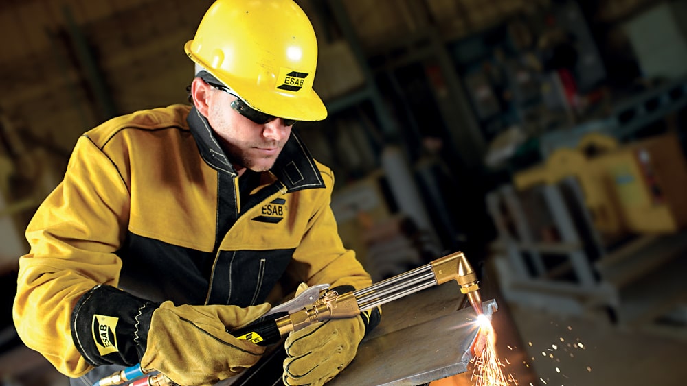
During the cutting process, it is important to protect yourself from flying sparks, slag and bright light. Make sure to wear personal protective equipment designed for welding and cutting operations. These include goggles with tempered lenses, gloves, aprons and safety shoes. Keep your clothes free of oil or grease as sparks can quickly set them on fire.

Safety of Cylinders

Oxygen cylinders are painted green and contain oxygen compressed up to 2,200 psi. An accidental fall can damage the cylinder valve turning the cylinder into a lethal projectile. Chain the cylinders to prevent an accidental fall.

Acetylene and oxygen are stored in separate cylinders. If you are using oxy-acetylene, always light the acetylene gas first. If you are using alternative fuel gases with oxygen, you can light the torch with both gases flowing.

Oxygen Regulator Valve

Dust and dirt in the regulator valve can ignite if it comes into contact with oxygen. Vent the regulator valve before attaching it to the cylinder to blow any dust or dirt away. Ensure the filter in the regulator inlet is always clean and in place.

To prevent any strain or sudden surge on the regulator, it is recommended to open the oxygen cylinder valve slowly. While doing so, remember to stand to one side.

It is important that you purge each hose independently. To do this, open the valves one at a time for a few seconds.

Keep Away From Oil or Grease

Every regulator gauge is printed with the expression, “use no oil”. Never clean the connection or regulator with oil or grease. Before handling cylinders, make sure to keep your gloves and hands free of oil or grease.

Oxygen can burst into flames when in contact with oil or grease. Always open the cylinder valve slowly. If the cylinder valve is opened quickly, then the heat of recompression generates an ignition temperature. The presence of oil or grease and oxygen in the area can cause a dangerous explosion.

Tip Size and Pressure

Use the correct tip size and pressure as each tip is designed for a specific pressure. Too much pressure can cause the system to back-pressure and reverse flow. Too little pressure can cause the tip to sputter and pop resulting in flashback or backfire.

While the oxy-fuel process can be hazardous, taking proper safety precautions can prevent injuries and keep your equipment running smoothly and efficiently.

Posted on

How Does the Oxy-fuel Cutting Process Work?

Oxy-fuel Cutting – Step by Step Process, Characteristics and Application

ESAB’s experience with oxy-fuel cutting dates to 1907. Oxy-fuel cutting is regarded as the most cost-effective process for carbon steel cutting. One of the greatest advantages is that the process can be combined with plasma or waterjet on the same part. In the present article, you will learn how the oxy-fuel cutting process works.

What Is Oxy-fuel Cutting?

Oxy-fuel cutting is a process where a mixture of fuel gases and oxygen is used to cut metals. Some of the commonly used fuel gases include propane, natural gas, acetylene and a few other mixed gases. The technique is immensely popular on CNC machines for cutting steel plates.

How Does the Oxy-fuel Cutting Process Work?

Oxy-fuel cutting is a chemical reaction between pure oxygen and steel to form iron oxide. It can be described as rapid, controlled rusting. An oxy-fuel cutting torch with a flame is used to cut shapes out of plate steel.

Here are the basics of how the oxy-fuel cutting process works:

Step1: Preheat

Before cutting the steel, the metal is to be heated up to its kindling temperature, about 1800°F with preheat flames. This makes the steel readily react with oxygen. An oxy-fuel torch is used to provide preheat flames to heat the metal.

Fuel gas is mixed with oxygen inside the torch to form a highly flammable mixture. The torch has a nozzle containing multiple holes designed in a circular pattern to focus the flammable gas mixture into multiple little jets. This fuel-oxygen mixture gets ignited outside the nozzle. The resulting preheat flame forms at the nozzle tip. Adjusting the fuel-to-oxygen ratio enables to adjust the preheat flame to produce the highest possible temperature in the smallest possible flame. This helps to concentrate the heat on a small area on the surface of the steel plate that is to be cut.

Step 2: Piercing

On application of preheat flame, the surface of the plate reaches kindling temperature (approximately 1800°F). Pure oxygen is then directed towards the heated area in a fine, high-pressure stream to pierce through the plate. This is known as “cutting oxygen”. When the cutting oxygen stream hits the preheated steel, a rapid oxidation process begins. The oxidised steel changes into molten slag. The slag needs to be removed to allow the stream of oxygen to pierce through the plate. Depending on the plate thickness, the oxygen stream is pushed deeper into the plate. In the process, the molten slag gets blown out of the pierced hole.

Step 3: Cutting

When the oxygen stream pierces through the plate, the torch can be moved at a constant speed to form a continuous cut. The molten slag formed during the process is blown to the bottom of the plate.

The heat generated during the chemical reaction between the oxygen and the steel preheats the surface of the plate but just in front of the cut. However, this heat is inadequate to perform cut without preheat flame. Therefore, preheat flame is used throughout the cut to add heat to the plate as the torch moves.

Does Oxy-fuel Cutting Process Work on All Metals?

Only metals whose oxides have a lower melting point than the base metal itself can be cut with this process. Otherwise, as soon as the metal oxidises, it terminates the oxidation by forming a protective crust. Only low carbon steel and some low alloys meet the above condition and can be cut effectively with the oxy-fuel process.

Characteristics of High-Quality Oxy-Fuel Cut

A quality oxy-fuel cut has the following characteristics:

  • Square top corner (with minimum radius)
  • Cut face flat top to bottom (no undercut)
  • Cut face square with respect to the top surface
  • Clean smooth surface with near vertical drag lines
  • Little to no slag on the bottom edge (easily removed by scraping)

These are just the basics of oxy-fuel cutting. Some of the factors that affect the quality of the cut edge include cut oxygen pressure, plate temperature, cut oxygen pressure, preheat flame adjustment, speed, cutting height, etc.

Various Applications of Oxy-flame Cutting

Oxy-fuel cutting is extensively used to make plate edges for groove and bevel welding. The cutting process also finds its use in:

  • Manual rough severing
  • Scrap cutting
  • Automated precision contour cutting
  • Metallising
  • Cutting and bending
  • Flame hardening

Oxy-fuel cutting process is cost-effective and workable on metals of varying thicknesses. Therefore, the process finds application in field repair work and construction sites.

Posted on

10 Tips for Using Compact MIG Welders

10 Tips to Set-Up and Use Compact, Integrated MIG/MAG Welders

Benefit from Advanced Welding Features

Recently there’s been a migration to transfer the features and benefits of heavier industrial machines into light industrial welders – and offer them at affordable prices. This movement meets the diverse needs of welding professionals and first-time welders, however advanced performance doesn’t matter until a machine is set up correctly. Here are some tips to set up MIG/MAG welders with integrated wire feeders, such as ESAB’s Rogue EM & EMP Series, as well as a look at some of their newest capabilities.


1.    Installing the MIG torch and feed rolls
For positive wire feeding performance, feed rolls must match the wire diameter and type. To flip or install a new feed roll, release the pressure roller arm, and remove the feed roll retention knob. Use a smooth-groove drive roll for solid wire and a V-knurled roll for flux cored wire. For aluminium, use a spool gun for better feeding performance of this soft wire.


2.    Setting the feed roller tension 
Proper tension on the feed rolls is essential for consistent welding performance – you want to add just enough tension to prevent the wire from slipping. To check tension, hold the torch nozzle 3 mm from a non-conductive surface. Pull the trigger, and the feed rollers should start to slip. Now hold the torch 50 mm from the surface. The wire should feed out and bend – this indicates proper tension. If the wire stutters because the feed rolls slip, add tension in half turn increments.


3.    Setting wire brake tension
After installing the wire spool and before welding, you need to set the wire brake tension. To do this, turn the nut clockwise to apply more tension and counter-clockwise to release tension. The brake is correctly adjusted when the spool stops within one-half to two inches after releasing the trigger. The wire should be slack without becoming dislodged from the spool. If the wire spool stops immediately after releasing the trigger, there’s too much tension on the spool.


4.    Choosing and installing consumables
To ensure proper arc performance, you must use the correct contact tip size that corresponds to the wire diameter used. Before installing the contact tip, note that the torch liner is present at the end of the conductor tube. Now slip the tip over the welding wire, seat it into the conductor tube or gas diffuser, thread contact tip into diffuser and screw on the shielding gas nozzle.


5.    Choosing the correct gas
To MIG/MAG weld steel with the short circuit transfer mode, a mixed gas blend of 82 percent argon and 18 percent CO2 is suitable for most applications, as it creates the least amount of spatter, the best bead appearance, and helps prevent burn-through on thinner materials. You can also use 100 percent CO2 for deeper penetration on thicker sections. It costs less, but produces more spatter and a rougher-looking bead.

To spray transfer weld, use a mixed gas with a higher argon content, such as 90/10. To MIG/MAG weld stainless steel, most welders use a “tri-mix” gas blend with Helium, Argon and CO2, alternatively, 98 percent argon and 2 percent CO2 And finally, to MIG weld aluminium and silicon bronze, welders use 100 percent argon.


6.    Installing a regulator and setting gas flow
Stand on the opposite side of the cylinder, point the valve opening in a safe direction and crack the cylinder valve to clear any dust and close it quickly. Install the regulator by threading the large nut onto the cylinder and use a wrench to tighten the nut (always use a wrench to tighten metal-to-metal connections).

For welding with typical wire diameters, set the gas flow rate to approximately 10 – 12 LPM. If you notice porosity, or for welding in mildly breezy conditions, increase flow rates to 15 LPM. Do not increase flow rates beyond 15 LPM as excessive rates create turbulence that can pull in outside air and contaminate the weld.


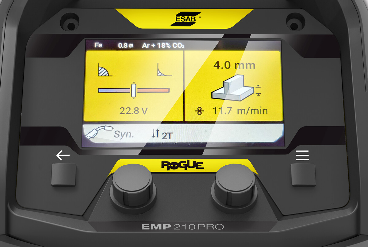
7.    Manual MIG/MAG or Synergic MIG/MAG?
In manual mode, you fine tune the arc by adjusting voltage and wire feed speed (tips on that shortly). Synergic MIG offers one knob control and takes the guesswork out of fine tuning the arc. It makes the machine easy to set up and even easier to adjust. Use the digitally-driven menu to select the wire type, wire diameter and gas combination. With that information entered, you can weld thicker or thinner metal just by increasing or decreasing wire feed speed; the machine will adjust other parameters automatically. A “trim voltage” control (which controls voltage in manual mode) enables you to adjust the weld bead profile, typically to create a flatter bead with better wet-out at the toes of the weld.


8.    More Functions

Digital controls and advanced displays on machines such as ESAB’s Rogue EMP 210 PRO provide access to such functions as:

  • Trigger selection mode to select between four trigger modes: 2T (standard operation), 4T (trigger latch), spot weld and stitch weld.
  • Memory functions to store and recall favourite job parameters.
  • The ability to set and adjust gas pre-flow time, creep start or run-in speed, burnback time and gas post-flow time.
  • Arc Dynamics (see below).
  • Other items include lists of wear and spare part numbers, general maintenance practices and even the owner’s manual.

9.    Understanding Arc Dynamics 
Arc Dynamics allows you to adjust the intensity of the welding arc on a scale, such as from -9 to +9. A lower setting makes the arc softer with less weld spatter and has better wetting action of the weld puddle. Higher arc control settings give a more driving arc which can increase weld penetration.


10.    Fine tuning your MIG/MAG arc
To fine tune your MIG/MAG arc, start by using an amperage that matches the wire diameter, shielding gas and material thickness. Voltage controls the height and width of weld bead, as well as the wire melt-off rate.

A finely tuned MIG arc in the short circuit transfer mode has a “sizzling bacon” sound that signifies a proper balance of wire feed speed and voltage. A harsh sound with a lot of pops usually means that the wire is melting faster than it is coming out of the torch. To solve the problem, decrease voltage or increase wire feed speed. If the wire stubs into the base metal, there is not enough voltage to melt the wire. Solve this by increasing voltage or reducing wire feed speed.

Posted on

4 Main Types of Welding Positions

4 Popular Welding Positions and Tips for Great Results

Each welding position requires different techniques, preparation and parameters. Understanding the welding positions will help you choose the right filler metal and welding process.

Welding Position

Welding position is a technique of joining metals in the position in which the component will be used.

Types of Welding Positions

There are 4 main types of welding positions, which include:

  1. Flat welding position
  2. Horizontal welding position
  3. Vertical welding position
  4. Overhead welding position

Flat Welding Position

Also known as the downhand position, the flat position is the easiest of all the welding positions. A flat position is the common type of weld. It is the first weld that beginners learn. In this position, you are not welding against gravity. The workpieces that are to be welded are placed flat. An electric arc is passed over the workpieces in a horizontal direction. The top surface of the joint is welded allowing the molten metal to flow downwards into the joint groove or edges. A flat position can be welded with any welding process. Make sure to follow the recommended techniques for the process.

Horizontal Welding Position

A horizontal weld is considered an out-of-position weld. It is more challenging to perform than vertical and overhead positions and requires higher skill. In the horizontal position, the weld axis is roughly horizontal. The position is executed based on the type of weld. For a groove weld, the weld face is along a vertical line. In fillet weld, the weld bead is done where the horizontal and vertical surfaces of the metals meet at 90°. Horizontal weld has many similarities with the flat position.

Vertical Welding Position

The weld and plate lie vertically in the vertical welding position. Vertical welds can be done in two ways:

  • Vertical up (during welding moving from bottom to top in the weld joint)
  • Vertical down (during welding moving from top to bottom in the weld joint)

Vertical up is mostly used on thicker materials and on large weldments where it is difficult to move to flat or horizontal position.

One of the major challenges of vertical welding position is that the force of gravity pulls the molten metal downwards and piles up the metal. Welding in a downhill or upwards vertical position can help prevent this issue.

When working on vertical weld make sure you are comfortable in a position. You can initially practise on scrap material to ensure the techniques and parameters that you are using produce the required result. This way you can make the adjustments before welding on the workpiece.

Overhead Welding Position

The overhead welding position is done from the underside of the joint. It is the most difficult and complicated position requiring a high skill level. In this position, the welding is done with the metal pieces above the welder. Therefore, welders mostly find themselves lying on the floor for overhead welding. Make sure to find the most comfortable position to gain easy access to the joint for welding.

Overhead welds are mostly used on metals or fixed equipment that cannot be moved. One of the major issues in the overhead weld is that the deposited metal to the joint tends to sag on the plate. This results in beads with higher crowns. To prevent this, make sure to keep the molten puddle small. If the weld puddle is large, the welder needs to remove the flame for a moment to allow the molten metal to cool.

When welding in an overhead position the sparks drop down. Make sure you have extra protection, such as a bandana under your welding helmet. Stick welding produces more sparks and splatter. Using a full leather welding jacket offers protection from sparks and splatter.

Conclusion

When you start working on a welding position, it is always a good idea to perform a few practice passes before welding to ensure you complete the entire weld length in a comfortable position. Being in a comfortable position is pertinent to achieving a consistent weld.

The filler metal you choose and mode of transfer determine the welding position you should go for. If you want to weld overhead, then make sure the filler metal is capable of it and adjust your welding parameters to help optimise the overhead welding position.